How to Solve “Unkown error” Caused by Endnote in Word 2007

Today, my word 2007 doesn’t work suddenly. I would get a “An unknown error occurred” message with title “Endnote X2” (shown below) when I tried to open or edit any word files.

Endnote X2 unknown error

Endnote X2 unknown error

This drove me crazy, I uninstalled and reinstalled word 2007 several times, still nothing new happened. Finally, I got the answer.  Here’s solution from Microsoft Help and Support website.

Original website link: http://support.microsoft.com/kb/921541

Delete the Word Data registry key

Most of the frequently used options in Word are stored in the Word Data registry key. A common troubleshooting step is to delete the Word Data registry key. The next time that you start Word, Word rebuilds the Word Data registry key by using the default settings.

To view these options in Word 2002 or Word 2003, click Options on the Tools menu.

To view these options in Word 2007, click the Microsoft Office Button, and then click Word Options.

Continue reading ‘How to Solve “Unkown error” Caused by Endnote in Word 2007’

Finite Element Analysis of Cantilever Beam(II)

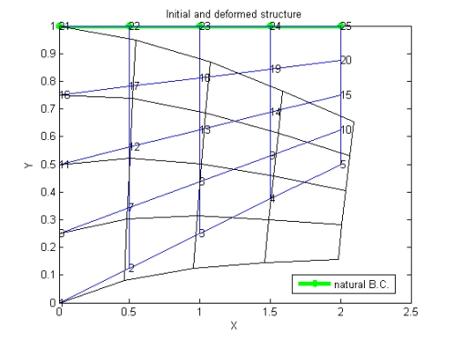
deformed structure

Maximum displacement in y direction is -0.3752×10e-4m and in x direction is 0.102×10e-4m.


Matlab Result (16 element)

Matlab Result (16 element)


Gauss Point maximum stress in X direction is 288.83Pa

Gauss Point minimum stress in X direction is -259.6Pa

Maximum stress in X direction is 335.77 Pa

Minimum stress in X direction is –245.89 Pa


Matlab Result (64 elements)

Matlab Result (64 elements)


Maximum displacement in y direction is -0.4124×10⁻⁴m and in x direction is 0.1117×10⁻⁴m.


Matlab Result (64 elements)

Matlab Result (64 elements)


Gauss Point maximum stress in X direction is 387.23Pa

Gauss Point minimum stress in X direction is -294.74Pa

Maximum stress in X direction is 430.85 Pa

Minimum stress in X direction is –298.61 Pa

ABAQUS RESULT (16 ELEMENTS)

Continue reading ‘Finite Element Analysis of Cantilever Beam(II)’

Finite Element Analysis of Cantilever Beam(I)

Problem Statement

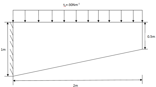
A cantilever beam is subjected to a uniform distributed load with value 30 N/m. The trapezoid beam has right vertical length 0.5m and left vertical length 1m. And top length is 2m.as shown in the graph.

geometry

B.C.: The vertical left side is fixed; the bottom and the vertical right side are free.

Material properties: isotropic material   E=3×10⁷Pa Poisson’s ratio ν=0.3

Regard this problem as a plane stress one. (beam width is 0.1m)

Math expression of the problem

PDE:

pde1

Boundary Conditions:

bcwhere

bc2bc3

Continue reading ‘Finite Element Analysis of Cantilever Beam(I)’

How to establish a sandwich plate in Hypermesh(III)

Here’s part of Carbon/Epoxy Sandwich plate key file which contains all the keyword in LS-DYNA.

=====================================================================

$$ HM_OUTPUT_DECK created ****** by HyperMesh Version 9.0b122
$$ Ls-dyna Input Deck Generated by HyperMesh Version : 9.0b122
$$ Generated using HyperMesh-Ls-dyna 971 Template Version : 9.0-SA1-019
*KEYWORD
*TITLE
Carbon/Epoxy
*CONTROL_TERMINATION
$$ ENDTIM ENDCYC DTMIN ENDENG ENDMAS
5
*DATABASE_BINARY_D3PLOT
$$ DT/CYCL LCDT BEAM NPLTC
1.0000E-02
0
*NODE
1 1.0 1000.0 70.0
2 0.0 1000.0 70.0
………
6029 0.0 0.0 0.0
6030 1.0 0.0 0.0
*MAT_ORTHOTROPIC_ELASTIC
$HMNAME MATS 2facesheet
21.5800E-06 55.02 55.02 10.792 0.29 0.248 0.248
21.319 4.953 4.953
Continue reading ‘How to establish a sandwich plate in Hypermesh(III)’

How to establish a sandwich plate in Hypermesh (II)

Response to a full-span blast pressure

The load is added on the whole surface of the top facesheet in these three design, this section provides the global and local response of the sandwich plate under blast loading.

Local and overall deformations

T=0.25 ms

T=0.25 ms

T=0.5 ms

T=0.5 ms

T=1 ms

T=1 ms

T=2 ms

T=2 ms

T=3 ms

T=3 ms

T=4 ms

T=4 ms

T=5 ms

T=5 ms

Fig. 7 Global deform of the Carbon/epoxy Sandwich plate

Here’s Carbon/epoxy Sandwich plate vedio

Continue reading ‘How to establish a sandwich plate in Hypermesh (II)’

How to establish a sandwich plate in Hypermesh (I)

This article presents a study of the conventional sandwich plate designs subjected to blast loads. In the conventional sandwich design consists of thin outer (loaded side) and inner facesheets made of fibrous laminates, separated by a layer of structural foam core. Two models’ facesheet materials are (1). (0/±45/90)s Carbon/epoxy (2).Steel. Comparisons of the two models are made during a long time period of 5.0 ms, initiated by a pressure impulse lasting 0.05 ms applied to a single span of a continuous plate. In the initial response phase the overall deflections are limited and considerable foam core crushing is caused in the 1st design by the incident compression wave. This type of damage is much reduced in the model (2) with Steel facesheet which leads to significant reductions in facesheet strains and overall deflection. The total kinetic energy of the model (2) with steel is much lower than that of a Carbon/epoxy plate, and so is the stored and dissipated internal energy.

Introduction

A sandwich structured composite is a special class of composite materials that is fabricated by attaching two thin but stiff skins to a lightweight but thick core. The core material is normally low strength material, but its higher thickness provides the sandwich composite with high bending stiffness with overall low density.

Open and closed cell structured foam, balsa wood and syntactic foam, and composite honeycomb are commonly used core materials. Glass or carbon fiber reinforced laminates are widely used as skin materials. Sheet metal like steel is also used as skin materials in some cases.
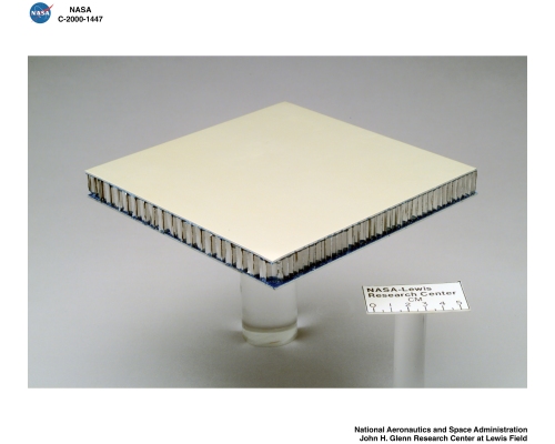
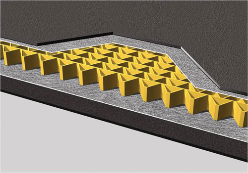
glare honeycomb

composite sandwich plate

Fig. 1 Sandwich Plate

Designs, material properties and loads

A multi-span sandwich plate supported by equally spaced rigid stiffeners is used. And it has assumptions as follows:

  1. The connections between the different layers are perfect.
  2. Assume moisture and temperature effects as zero.
  3. Assume voids in the composite are zero.

The length of the plate is L=1000 mm. The length of a single span between supports is L= 600 mm. The total width, measured in the X2-direction of Fig. 2 is assumed to be sufficiently large, so that the plate can be analyzed in plane strain, with displacements u2 = 0 everywhere. Width of the supporting stiffeners is d = 100 mm, such that the clear span of the sandwich plate is L-d = 400 mm.

Continue reading ‘How to establish a sandwich plate in Hypermesh (I)’

How to eastblish a 3D model in Hypermesh and output key file

This article will introduce a common procedure to establish a 3D model in Hypermesh pre-processor. And then output key file (or k file) in LS-DYNA format.

1. Load LS-DYNA user’s file and the template

2. Define the materials

3. Define the section(properties)

4. Define the part(component)

5. Create the load collector

6. Check the units(find it on a table)

7. Create the geometry of the model

· Create the node
· Create the line
· Create the surface
· Create the solid

Continue reading ‘How to eastblish a 3D model in Hypermesh and output key file’

Hello world!

Hi, this is a blog mainly about technology.

In the next few days, I will introduce how to use hypermesh as a pre-processor to establish a 3D model, and then use LS-DYNA as solver to simulate Strike, Shock and Blasting problems.

Original Journey © 2009


Archives